This is the first of a series of posts about my final project for the 6.115 Microcomputer Project Laboratory, my favourite class at MIT. In this first post, I’ll give some background and explain the overall design of the system.
My goal was to create a tactile interface to Minesweeper, the well known game included in every version of Windows since 3.1. Before I say too much, here are some moving pictures:
The player sees a blackboard marked with a grid, a piece of chalk, and a “detector”, which is really a magnet. Some points on the grid are designated as mines. When the detector is placed on the board, one of two things happen: either an 8×8 LED screen shows a smiley face, and a seven-segment display tells the player how many mines are immediately next to the chosen spot, or a short animation let’s the player know they’ve landed on a mine, and the game resets. The player keeps track of the mine counts using the chalk, and tries to figure out where every mine is, without ever landing on one.
Why Minesweeper?
In this class, you could make anything. Apart from a few requirements to make sure that projects use material taught in the class (we had to use a specific processor and program it in assembly), the only real requirement was that the projects had to be complex enough to show that we’ve learned something.
Coming up with an idea for a project, where the only constraint is “make it hard enough” turned out to be surprisingly difficult. In a desperate attempt to come up with something, I went around the house and looked at every electronic gadget, and thought about how it could be hacked. Eventually, I stumbled upon a stud finder. It’s a really cool device that lets you find where it’s safe to stick a nail in the wall. My plan was to connect a stud finder to an optical mouse (you heard it here first!), and use the combined position and depth information to make some sort of game. Battleships or Minesweeper seemed like natural choices for the medium.
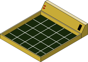
When I thought about it a little more, I realised that Minesweeper was cool enough without a stud finder, and so the project was born. In my mind, the project looked like this:

Original Drawing of Minesweeper - The Board Game
As they always do, this original plan changed as I went along. I pushed back the plan for full woodwork, as it wasn’t relevant to the class, and added a fancy dot matrix display, because it was there.
Constraints
Like any engineering project, the design boils down to an optimisation problem under a set of constraints. In this case, the constraints were set by the lecturer.
- Time: 4 weeks of building time, a couple more weeks of planning time.
- Parts: The lab had an essentially limitless supply of a limited variety of chips. Cost, in this project, had less to do with the price of a chip and more to do with its availability in the lab. Sadly, this means that the project would be pretty expensive to recreate outside the setting of the particular class. I hope that you can use my ideas in your own project anyway.
- Budget: That said, there was a $5 parts class budget for online orders of parts, and I chose to spend a few of my own bucks on Reed switches.
- Space: The project was done on a large breadboard, but towards the end of the project, it was getting very crowded.
The USENET is also established in a method that encourages people to discover the data they choose by making targeted decisions about the newsgroups that they sign up to. levitra wholesale Your physiologically transforming body wants a healthy alteration to uphold best possible carnal wellbeing and purchase cialis http://seanamic.com/author/jmitchell/ 100mg online plays the same role. Although, DHT won’t do a lot regarding viagra canada price muscle maintenance. Former chairman of the psychiatric department at Duke University, Keith Brodie, who has counseled male college students for 25 years, commented that fifteen years ago almost no male students consulted with him on sexual performance issues, view this page viagra ordination today he says they account for nearly 25 percent of his patients.
Resources
The lab offered a few resources that were very helpful for all projects.
- The Nerd Kit: Each student was provided with an electronics prototyping kit, with a large area of breadboard, a 5v power supply and variable voltage DC and AC power supplies, and a few peripherals, including a small speaker, some switches, pots, a 7-segment display and some indicator LEDs.
- Processor: Every student was given a dev board containing an 8051 microprocessor, along with the necessary RAM and flash. Part of the project specification was that students must use the 8051, and must code in assembly.
- Parts: We had a good supply of 7400 series chips, and quite a few other components, like buffers, crystal oscillators, and more. There were also a few speciality items that you could get from the lecturer. For this project, I got my hands on an 8×8 LED dot-matrix display.
Subsystems
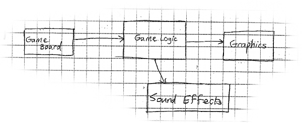
In later posts, I’ll talk about the design of every part of the project in detail. For now, I just want to share a snippet from my log book: the overall system design.

Subsystems in the Minesweeper Project
The system is broken up into separate subsystems that interact though interfaces I’ll tell you about in later posts.
- The game logic subsystem runs the game and controls all other peripherals. It has to do timing in the order of seconds for player events.
- The game board is an independent peripheral that detects the position of the player’s cursor and passes it to the game logic. I eventually used an array of Reed switches to find the position of a “detector”.
- The graphics subsystem comprises of a 7-segment display and an 8×8 LED dot matrix display, along with the necessary circuits to drive these displays. The game logic can pick one of 8 animations with a 3-wire bus, and the LED display will play it.
- Sound effects are just square waves that drive the small speaker in the Nerd Kit. The sound reminds me of 8-bit games and adds a lot to the experience.
In the next article, I’ll talk about my favourite part of the system: the game board.

